
Table of Contents
Liabilities of Refueling a Customer Spacecraft
After LEO Speedwagon has successfully demonstrated its ability to extract and store water ice, our group needs to demonstrate the ability to refuel another spacecraft/satellite in Low Earth Orbit. This technology demonstration will be conducted using rendezvous and proximity operations without any damage to the structural integrity of both spacecraft involved.
Our group affirms its adherence to the Convention on International Liability for Damage Caused by Space Objects (1972), Article 3:
“In the event of damage being caused elsewhere than on the surface of the Earth to a space object of one launching State or to persons or property on board such a space object by a space object of another launching State, the latter shall be liable only if the damage is due to its fault or the fault of persons for whom it is responsible.”
and Article 4:
“1. In the event of damage being caused elsewhere than on the surface of the earth to a space object of one launching State or to persons or property on board such a space object by a space object of another launching State, and of damage thereby being caused to a third State or to its natural or juridical persons, the first two States shall be jointly and severally liable to the third State, to the extent indicated by the following: (a) If the damage has been caused to the third State on the surface of the earth or to aircraft in flight, their liability to the third State shall be absolute; (b) If the damage has been caused to a space object of the third State or to persons or property on board that space object elsewhere than on the surface of the earth, their liability to the third State shall be based on the fault of either of the first two States or on the fault of persons for whom either is responsible. 2. In all cases of joint and several liability referred to in paragraph 1 of this article, the burden of compensation for the damage shall be apportioned between the first two States in accordance with the extent to which they were at fault; if the extent of the fault of each of these States cannot be established, the burden of compensation shall be apportioned equally between them. Such apportionment shall be without prejudice to the right of the third State to seek the entire compensation due under this Convention from any or all of the launching States which are jointly and severally liable.”
It is important to note the Liability Convention has never been invoked even though several spacecraft collisions have occurred in the past (French satellite Cerise hit by an expanded Arianne rocket, Cosmos 2251/Iridium 33 in 2009; 2013 collision between Fungyun FY-1C and the Russian BLITS nano-satellite). LEO Speedwagon is cognizant of the challenges associated with rendezvous and proximity operations and will use all available technological aids to enhance our situational awareness.
In addition, our group confirms its commitment to abiding by the OST, Article VII:
“Each State Party to the Treaty that launches or procures the launching of an object into outer space, including the Moon and other celestial bodies, and each State Party from whose territory or facility an object is launched, is internationally liable for damage to another State Party to the Treaty or to its natural or juridical persons by such object or its component parts on the Earth, in air or in outer space, including the Moon and other celestial bodies.”
Customer Spacecraft Capture, Docking, and Berthing Systems
The idea of using a spacecraft to fuel another is nothing new. The Orbital Express from the Defense Advanced Research Projects Agency (DARPA) program was to demonstrate fully autonomous on-orbit satellite servicing capabilities (Bond, 2008). When beginning the event of refueling a customer spacecraft, the first step that must be completed is the mating of the spacecraft to the 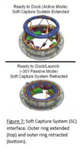 refueling station. Due to the fact that the International Space Station is being utilized for this project, the International Docking System Standard (IDSS) can be used to conduct the process. This process is outlined in the IDSS Interface Definition Document (IDD) (2011) and is a result of the collaboration of all parties involved in the International Space Station. The document allows for joint collaborative endeavors through the outline, establishment, and implementation of a standard docking interface. Utilizing validated designs and technologies, this docking method is already in place on the ISS and must be utilized by all customer space crafts to ensure a high probability of successful craft mating.
Once orbital rendezvous has taken place between the space station and customer spacecraft, the first stage of the IDSS two-stage docking and berthing approach on the ISS begins to occur. This mechanism that conducts the first stage is called the Soft Capture System (SCS) (Figure 7) and must also be present on the customer spacecraft. It is responsible for the initial capture and stabilization of the vehicle and is important, as it allows for low-impact docking. The system is made up of a docking ring with electromagnets and mechanical capture latches with mechanical strikers, which create an initial low-force structural mating between the docking systems. For a customer spacecraft to be fully compatible with the IDSS implemented on the ISS, its SCS must have the implementation of both these capture tools. To allow for correct navigation of the customer spacecraft into the SCS docking port, its compliant system must include a series of three metal guidance petals (Figure 8) that are equally spaced around the circumference of its own SCS outer ring. The outer rings are extended outward and the SCS systems are led together by the guidance petals, they obtain contact with opposites, creating a soft capture magnetic force. Once this process has been completed, the mechanical latches around the outer rings engage into a locked position, grasping the other and creating a mechanical hold on the two crafts. The two SCS outer rings can then retract, slowly pulling the vehicles together and positioning them for the next docking step (International Docking Standard Interface Design Document, 2011.).
After the SCS has completed its job, the second stage of the IDSS docking approach can take place. The next mechanism which kicks into action is called the Hard C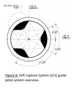 apture System (HCS) (Figure 9) and is responsible for the final structural mating of the two crafts. This system is made up of tangential hooks, which are placed in 12 pairs. These pairs include one passive hook and one active
hook, creating a total of 24 attachment points. For a successful structural connection between the two crafts involved, one must engage 12 passive hooks, while the other must engage 12 active hooks. After the hooking process is completed, the force required to press the seals within the docking systems will be achieved and a successful docking will be obtained (International Docking Standard Interface Design Document, 2011.).
Once the capture systems have completed docking and refueling of the customer spacecraft has been conducted, spacecraft undocking can take place. This act of undocking is also described in the IDSS and is implemented through use of a retractable separation system. For separation, the undocking spacecraft 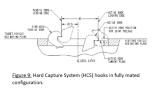 utilizes a set of plungers. The exact number of plungers is left to the docking system designer; however, it must comply with striking areas on the HCS. After the SCS and HCS mechanisms disengage, the plungers will push the vehicle off and then get remotely retracted into the corresponding spacecraft with the use of any external force (International Docking Standard Interface Design Document, 2011). Once the spacecraft is far enough away from the space station, a separation burn will occur to increase the distance between the two. At this point, the customer spacecraft can then fire its engines and begin its journey into deeper space (NASA, 2010).
Robotic Refueling and Servicing Tools
The final phase for this mission is the refueling of another spacecraft. After capture, berthing, and docking of the customer spacecraft occurs, this refueling process can begin. To carry out this task, tools from NASA’s Robotic Refueling Mission (RRM) will be utilized. The tools from this NASA mission were launched to the International Space Station in two separate batches in 2011 and 2013 (NASA: What is RRM, n.d.). This is an important factor for the LEO Speedwagon mission, as this means these tools are already in place on the space station and extra costs will not need to be allocated for their launch. The tools from the RRM mission are used in conjunction with the ISS robotic arm, Dextre, and are used to demonstrate the refueling and servicing of satellites in space.
To begin, the RRM mission tools packaged together are about the size of an average toaster and only weigh 7.5 kg. This means they will occupy a small volume of the space station, allowing for more room for other necessary hardware. The RRM package is made up of a Wire Cutter and Component Manipulation Tool, a Multifunction Tool, a Safety Cap Tool, a Nozzle Tool, and a VIPIR Inspection Tool, which capabilities include the following:
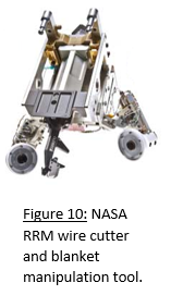
- Wire Cutter and Component Manipulation Tool (Figure 10): Capable of precision and fine-grabbing capabilities, thus allowing the cutting of small wires and the movement of delicate components, such as thermal blankets. In addition to cutting wires, this tool also includes a spade bit, which can slice tape that holds the thermal blankets in place. Finally, this tool contains jaw grippers that can grab onto a satellite or customer spacecraft’s appendages (NASA: What is RRM, n.d.).
- Multifunction Tool (Figure 11): Using four unique adaptors, which can be attached or removed by the system itself, this tool can capture and remove different types of caps and gas plugs from the craft it is working on (NASA: What is RRM, n.d.).
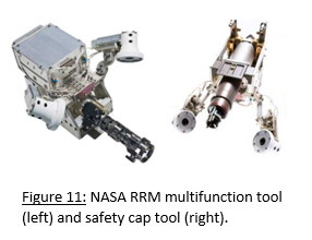
- Safety Cap Tool: Capable of removal and stowage of typical fuel-valve safety caps and seals. This tool also includes an adaptor which can be added or removed by the system itself, which allows the tool to manipulate screws and caps (NASA: What is RRM, n.d.).
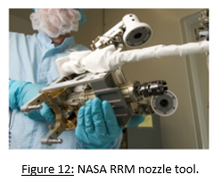
- Nozzle Tool (Figure 12): Capable of opening and closing a satellite or space craft’s fuel valves. In addition, this tool is connected to a hose, which allows for the transfer of fuel in a continuous loop process. An important feature of this tool is that it includes anti-cross-threading capabilities, which ensures that fuel caps will be screwed on correctly, thus avoiding risks of damaging the customer spacecraft’s fuel valve. Another great feature which this tool includes is that upon replacement of the fuel cap, it can swap the original cap for a “quick disconnect” cap that will allow easier connection to the craft’s fuel valve in future rendezvous (NASA: What is RRM, n.d.).
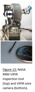
- VIPIR Inspection Tool (Figure 13): The Visual Inspection Poseable Invertebrate Robot (VIPIR) tool is a component of the RRM hardware set that allows for near and midrange inspection capabilities. Firstly, the near inspection capability is achieved through 32 inches of flexible, extendable, and navigable wire that houses a small camera on its tip. The VIPIR wire camera can be used to navigate the camera into small, tight space, being able to rotate up to 90 degrees in four different directions. In addition, this camera also includes an integral light that can illuminate the work surface on command. To complete midrange inspection capabilities, this tool uses two additional cameras, starting with an optical zoom camera that is about the size of a roll of quarters. Zooming in is conducted through use of two motors, which can view details down to 0.02 inches. The second midrange inspection camera does not contain a zooming option, unlike the first; however, this camera is used to assist mission controllers in the deployment of the wire camera. Giving them a larger viewing area, this camera shows the overall area of the workspace, allowing for precision navigation as the wire camera makes its way into the satellite or spacecraft (NASA: What is RRM, n.d.).
In addition to the main capabilities of these tools, each of the five includes two integral cameras that are aimed at the tool’s tips, which house built-in LEDs. Upon their operation, these cameras point directly at the work surface and give the mission controllers an illuminated first-hand view to monitor each of the tool’s positions. Along with using the cameras as a source of vision and tracking, the tools also have visual cues implemented amongst their surfaces. To ensure that each tool performs correctly, built-in fault tolerances are also in place so that mission success can always be achieved (NASA: What is RRM, n.d.). Though these robots must be controlled by human operators via ground control, the fact that no human operators are needed in space allows for this project to maintain a human-less presence on the space station itself
In regards to the LEO Speedwagon mission, these tools from NASA’s RRM mission will be utilized when conducting two tasks. The first of these tasks is the refueling of customer space crafts. Refueling will be possible, as the RRM toolset has demonstrated successful completion of robotic gas fitting removals, fuel valve manipulation, and fluid transfer events. The second task which the RRM toolset will conduct for the LEO Speedwagon mission is the inspection and service of the prospecting and mining spacecrafts. This task will be possible, as the RRM toolset has proven its capabilities for spacecraft inspection, through disassembling, cutting, component manipulation, internal and external viewing capabilities, and component reassembly. Additionally, as exemplified above, servicing can be conducted through the transfer of gas and various coolants. The successful demonstrations of these tools were conducted by NASA on the International Space Station between January 14th-25th, 2013, with Frank Cepollina, the associate director of NASA’s Goddard Space Flight Center Satellite Servicing Capabilities Office, speaking on the mission afterward: “RRM gives NASA and the emerging commercial satellite servicing industry the confidence to robotically refuel, repair, and maintain satellites in both near and distant orbits, well beyond the reach of where humans can go today.” (Alessandro, 2013.). With these capabilities being proven during events in both 2011 and 2013, the NASA RRM toolset will play a key role in the success of this mission’s main objectives (NASA: What is RRM, n.d.).
Navigation
Phase Three
Future Considerations
Home