
Table of Contents
A Station to Build Upon
The ISS was only made possible by years of research and learning from other space stations. Lessons from the Saylut, Skylab, and MIR paved the way for the ISS in terms of guidance stabilization, communication, and construction of habitats in space. The ISS consists of fifteen large cylindrical sections that inhere of laboratories docking compartments, airlocks, nodes, and living quarters. Also included are non residential components of the solar trusses and thermal radiators (Sabharwal, 2016). Construction began in 1998 and finished in 2012 from the help of several space agencies (NASA, ESA, Roscosmos, JAXA, and CSA). The ISS weighs 454 tons and uses 3.3 million lines of software code. The solar arrays have a voltage ranging from 130 to 180 volts and when not in direct sunlight relies on rechargeable nickel-hydrogen batteries to provide continuous power (Sabharwal, 2016).
The Functional Cargo Block (FGB) was the first element of the International Space Station, built in Russia under a U.S. contract. During the early stages of ISS assembly, the FGB was self-contained, providing power, communications, and attitude control functions, but now it is used primarily for storage and propulsion (NASA, 2010). The engines on FGB are Correction and Docking Engines, Docking and Stabilization Engines, and Accurate Stabilization Engines. These engines use a N2O4 and UDMH (Unsymmetrical dimethyl hydrazine) fuel, and have 16 storage tanks holding a total of 5,760 kg of fuel.
Zvezda Service Module provides station living quarters, life support systems, electrical power distribution, data processing systems, flight control systems and propulsion systems (Dunbar, 2013). Zvezda has 2 main engines and 32 attitude control engines. The engines run on a mix of N2O4 and UDMH, and has 4 propellant tanks storing a total of 860 kg of fuel. Attitude control engines are multidirectional, and can receive fuel from FGB, the main service module or the Progress module. Being able to receive fuel from multiple locations is a fail-safe so that the engines are never without fuel if needed. The “reboosting” of the station is what keeps it in orbit.
The third module used for propulsion is the Progress M, which is a Russian cargo spacecraft. Progress is used for propellant resupply and for performing reboosts. For the latter, Progress is preferred over the Service Module (NASA, 2010). Progress is fitted with 28 multi directional engines for attitude control. These engines, once Progress is docked with ISS, can do orbital adjustments and deliver fuel. The current version of Progress M being used is Progress MS. Though updated with new software and some cargo compartments, the orbital attitude adjustment aspect has remained unchanged. The fuel that Progress does not use directly for attitude adjustments is then transferred to the FCB and Service Module for use in orbital and transitional propulsion adjustments (evading space debris, etc). Progress M’s stay attached to ISS if there is space in them for trash and debris and various other things not needed on the station anymore. It then detaches and burns up in the atmosphere.
Necessary New Technology
Creation of Additional Internal Volume
Currently we need an approximate volume of 2,500 cubic meters just for the storage of oxygen and hydrogen, plus any extra that is desired for storage of other materials (for example, these other materials could be precious metals contracted by one of the investors of the station). The ISS currently has a pressurized volume of just over 900 cubic meters. The plan is to use as much of this volume as possible to accommodate the new station. However, there may be modules that are either too old or do not serve the purposes needed for this project that need to be removed from the system. For example, a module that does not house any refining equipment might also not be suitable for serving as a storage tank for fuel and so serves little purpose to the mission. Any volume that needs to be replaced or added on will be done using inflatable modules from Bigelow aerospace that can be purchased as needed. These modules reduce the amount of mass in the launch vehicle; therefore, reducing the amount of propellant needed for launch and saving money. The Bigelow Expandable Activity Modules (BEAM) can be installed and inflated quickly on the ISS in approximately 10 minutes; the cost is greatly reduced compared to the normal methods of expanding a space station.
The concept of inflatable space modules dates back to the 1980s and 1990s when various technologies on expandable habitats were explored. The greatest advantage of using an inflatable module then a rigid module is that they are smaller and more flexible at launch yet expand four times its size in orbit (Harr & Abeelen, 2016; Valle, 2017). In 1998 billionaire Robert Bigelow purchase the rights to the patents developed by NASA for inflatable modules and began developing and testing their own version of inflatable modules. Before BEAM, Bigelow Aerospace designed, launched, and tested both GENESIS I & II. Both modules weighted 1.36 tonnes measuring 4.4m in length and 2.5m in diameter with 11.5 cubic meters of volume. Each module performed flawlessly, drawing power from its 8 Gallium Arsenide solar panel arrays that provided 1 Kw of power (Harr & Abeelen, 2016; Valle, 2017).
The B330 module (Figure 3) is one of these expandable modules that is manufactured by Bigelow Aerospace. The B330 module is a vast improvement over the BEAM model. The B330 model is 13.7 m long, 6.7 m diameter, weight 20 tonnes, and have a volume of 330 cubic meters (Harr & Abeelen, 2016; Valle, 2017) as compared to the 16 cubic meters of volume that BEAM contains. The main goal of this mo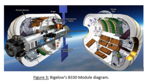 dule is to provide stand-alone habitation for humans in any space condition. For the purpose of the LEO refueling station, it could be used as storage for equipment, mining machines, resources and maybe someday people. If ISS could not reach the requirements for usable space for the refueling station, a BEAM or B330 could easily be implemented to make up the needed space.Universal docking methods on the refueling station make it possible to attach the modules. Right now BEAM is docked on the Tranquility node on the ISS. The Tranquility node houses the life support systems and environmental controls. Due to the fact that the LEO refueling station is unmanned, the Tranquility node would not need all the life support equipment in it. It could be gutted and used as a staging area for sorting resources and equipment to be stored in the BEAM or B330 inflatable module. Having inflatables in storage for use would make it possible to set up space in the event of last minute
 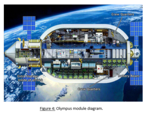 fueling needs, or resource receiving.
Looking towards the future of inflatables, Bigelow is also working on the concept of what they have named BA-2100 “Olympus” (Figure 4). It is an inflatable that is an astounding 2,250 sq meters when inflated, almost twice the size of the ISS currently. It has the capability to create its own space station, including 16 people, in one unit, which could be potential very applicable to the LEO space station design, should the ISS modules need replacing or expansion overall is needed for more missions. The goal is to have it ready for launch by the time the ISS is commissioned in 2024, and will use the Falcon Heavy rocket for launch.
Cryogenic Fuel Storage Tanks
Liquid rocket propellants have been used ever since the beginning of space travel and play a key role in this project (Wade, 2016). Propellants are created by combining two different types of chemicals; an oxidizer and a fuel. Upon their ignition, this chemical mixture burns and creates a large amount of thrust (Braeunig, 2008). When beginning the modification of the space station, one of the first component sets that must be added are the storage tanks for both elements of the rocket propellant being created; the oxidizer, liquid oxygen, and the fuel, liquid hydrogen. In the space industry, this type of propellant mixture is often given the name LOX/LH2.
To begin, LOX/LH2 is a cryogenic propellant, meaning that each of its components must be stored in very low temperatures to keep them in their liquid forms. In the case of oxygen, temperatures must be kept at a low temperature, around -182 degrees Celsius, while the hydrogen must be kept at an even lower temperature of around -253 degrees Celsius. These low temperatures will ensure that the chemicals remain a liquid and do not boil into a gaseous state (Wade, 2016). In addition to these requirements, pressure requirements are also necessary to ensure correct temperature and fluid flow from the tanks to the spacecraft being fueled. For liquid oxygen, this operating pressure ranges from about 138 kPa to 152 kPa, while the liquid hydrogen operating pressure ranges anywhere from 220 kPa to 235 kPa (NASA, 1988). Due to the very different temperatures and pressures for each component of this propellant mixture, the liquid oxygen and liquid hydrogen must be stored in two separate tanks.
When choosing the method for creation of these storage tanks, the team will contract the help of Lockheed-Martin, who worked with NASA to create 136 liquid oxygen and liquid hydrogen storage tanks for the Space Shuttle Program (Lockheed-Martin, 2013). In the case of the Space Shuttles, Lockheed-Martin engineered liquefied natural gas storage tanks that were built out of aluminum sections and fusion-welded together. Anti-vortex provisions can be implemented inside the tanks to dampen fluid motion and minimize liquid residuals (NASA, 1988). These tanks will then be connected to an input from the oxyhydrogen generator and to an output to the customer spacecraft refueling system through use of valves and hoses. The hose sizes will be determined to optimize the mass flow rate of the chemical in correspondence with the specific storage tank’s pressure. In regards to the input hose from the oxyhydrogen generator, a pressure valve will need to be used to ensure that the chemical inside the pressurized tank is not flowing back into the generator.
To keep the tank itself pressurized, it will be equipped with a pressure building valve (Figure 5). This type of valve works by pulling liquid from the temperature regulated tank and allowing it to 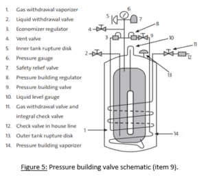 travel through a coil of hose that is wrapped around the tank’s external surface. As the liquid flows through this hose, it heats up, thus returning it back to a gaseous state. This hose is then connected to the opposite end of the tank, where the now higher-pressure gas is fed back inside. Before the gas can condense back into a liquid, its higher pressure creates pressure within the tank. The speed of this gas flow will increase to create more pressure, or decrease to lower the pressure, regulating it to meet the tank’s storage requirements (Air Products and Chemical Inc., 2013).
A major consideration when building these storage tanks is their volume, as they must fit within the given space station’s internal volume. When determining these numbers, an assumption was made that enough LOX/LH2 propellant needed to be present on the space station to refuel a customer spacecraft, the size of one of NASA’s Space Shuttles, and provide enough propellant for the craft to complete a round trip from the space station in low Earth orbit, to a satellite in geostationary orbit, and back to the Earth’s surface. This assumption was based on the fact that many communications and weather satellites are located in geostationary orbit and may need to be serviced or repaired. To calculate this propellant volume, which directly corresponds to the storage tank volumes of liquid oxygen and liquid hydrogen, the following process was conducted:
- Total change in velocity necessary to travel from the space station in low Earth orbit to a satellite in a geostationary orbit was calculated through use of a Hohmann transfer (Sellers et. al, 2007).
- Total change in velocity necessary to travel from a satellite in a geostationary orbit to the Earth’s surface was calculated through use of a Hohmann transfer (Sellers et. al, 2007).
- Total change in velocity for the round trip was calculated through summation of above velocity changes (Sellers et. al, 2007).
- Tsiolkovsky’s rocket equation was used to calculate total mass of propellant needed for the trip’s total velocity change (Sellers et. al, 2007).
- Assumptions:
- Spacecraft at hand is about the same mass as a NASA Space Shuttle
- Assumptions:
- The total mass of propellant needed for the trip, along with the densities of liquid oxygen and liquid hydrogen were used to calculate the volume of each storage tank (Sellerset. al, 2007).
- Assumptions:
- Mixture ratio of LOX/LH2 rocket propellant: 5:1 (Braeunig, 2008).
- Density of liquid oxygen at storage requirements: 1,140 kg/m3
- Density of liquid hydrogen at storage requirements: 71 kg/m3
- Specific impulse of LOX/LH2: 451s (Wade, 2016).
- Assumptions:
After the above calculations were completed, volumes for the storage tanks of each chemical were deduced. The space station will need a storage tank with a volume of 593.2 m3 to create sufficient space for the liquid oxygen and another storage tank with a volume of 1,904.93 m3 to create sufficient space for the liquid hydrogen.
Oxyhydrogen Generator
The key to generating rocket fuel from water mined on asteroids is being able to separate the components of the water into usable forms. To do this, an oxyhydrogen generator is used. An oxyhydrogen generator works off the premises of electrolysis, which is the process of passing an electric current through an ionic solution in order to force separation in compounds that by themselves are not spontaneous.
The key components of an oxyhydrogen generator are rather simple, consisting of a tank, a power source, anode and cathode electrodes, water, an electrolyte, and two smaller containers within the larger one to collect the generated gases. In space applications, this system will also consist of a valve system to vent the gases to external storage.
Inside the Oxyhydrogen generator, rather simple chemistry occurs in order to separate the hydrogen from the oxygen. 2H2O –> 2H2(g)+O2(g) is the reaction that is induced through electrolysis. In the compound H2O, Hydrogen has a +1 positive charge, while the Oxygen has a -2 negative charge. This is taken from standard Chemistry Oxidation charts. (The Catalyst, n.d.). In order to break down the compound, electricity is circulated through the liquid water. Electrons are pulled from oxygen molecules by the anode, and passed through the power system back through the cathode where they are attached to the Hydrogen (Figure 6). Due to the composition of water, twice as much Hydrogen is generated as Oxygen thus requiring twice as much volume to store it in.
To help facilitate this reaction, an electrolyte is needed. A similar system deployed on the ISS, known as the “Elektron” device utilizes Potassium Hydroxide (KOH) as its electrolyte and so it is assumed that this system will as well.
The selected electrolysis system will utilize a minimum voltage defined by V= Delta G/(z*F) in which V is the lowest required voltage for electrolysis to take place, z is the number of electron moles transferred per hydrogen mole (z=2) and F is the Faraday constant representing the charge on one mole of electrons (96,485 C/mol). Assuming water is kept at standard temperature (298.15 K) 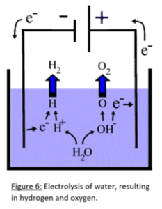 and pressure (1 atm) the thermal neutral voltage is 1.481 V. (Ursua et al., 2011)
Further, Faraday’s Law of Electrolysis states that the amount of the substances consumed or produced at the electrodes of an electrolysis cell is proportional to the charge that passes through the cell. This makes it possible to calculate how much current is needed over a given amount of time to create a specific amount of product. Charge is defined as current multiplied by time (C= I*t), a charge of 1 mole of electrons is equal to 96,485 C/mol. Utilizing this formula, the amount of moles of hydrogen and oxygen passed through at a given current can be calculated. Combining that with the Ideal gas law (V=nRT/P where n is the amount in moles, R is the ideal gas constant, T is temperature and P is pressure) will give a good estimate as to the volume at a given temperature and pressure. As an example, at standard temperature and pressure, 15 amps applied over 1 hour would result in 6.84 Liters of Hydrogen and 3.42 Liters of Oxygen.
In addition to the main components, several sensors are needed to ensure the safety of the overall system. These sensors include temperature sensors for the electrolyte mixture, pressure sensors for the Oxygen line, water storage tank, differential pressure between oxygen and hydrogen lines, and a sensor to detect electrolyte within both the oxygen and hydrogen line. (Oberg, 2010)
Two similar units when completed with accessories and sensors expended 3,385 Watt-hours per lb of O2 and 2,400 watt-hours per pound of O2. The Elektron-V system operated at an average power load of 860 watts producing up to 1,900 liters per day. (Oberg, 2010). The overall power requirement of the selected system will depend on the expected volume deliverance per hour. (Oberg, 2010)
Navigation
Phase Two
Phase Four
Home